硬件基础
因为我的是树莓派Model 3B+,所以GPIO引脚一共有40个
布局是这个样子的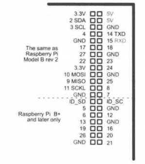
GPIO
发现了一个特别好用的,入门级GPIO库,之前看RPi.GPIO给我整蒙了,这个是真的简单
gpiozero
随便练了一下
RGB
一开始也是不太会接线的说,但是这个库比较简单就随便接了
R - pin17
G - pin27
B - pin 18
GND - GND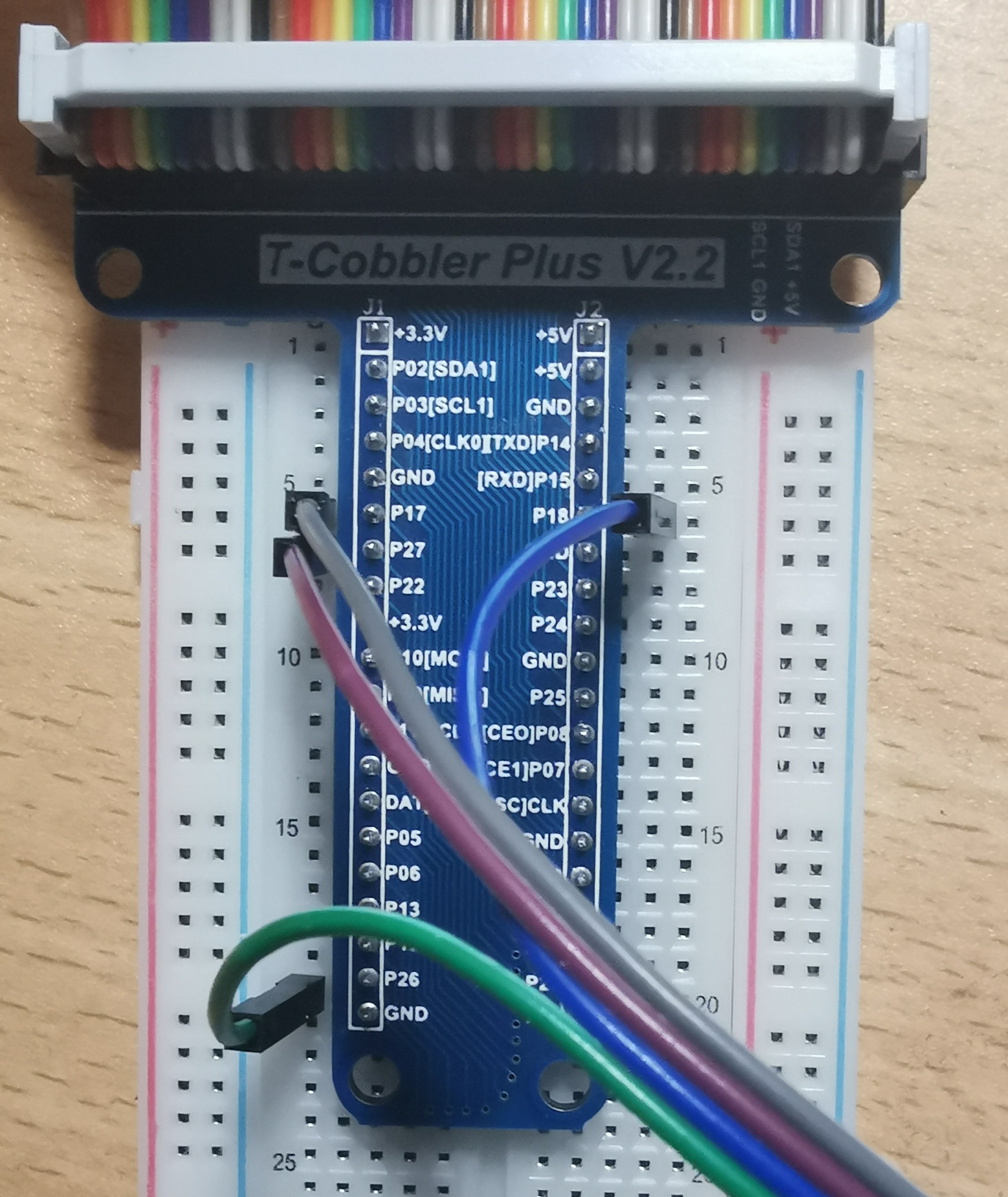
1 | from gpiozero import LED |
Button + RGB
一开始是青色,按按钮变紫色,松开又是青色
一开始把按钮的中间的线差错位置了,中间是正极连+5V,负极连GND,另一个边上的随便连个pin,我连的17
RGB灯就是换了一下pin,其他跟上面一样
1 | from gpiozero import Button, LED |
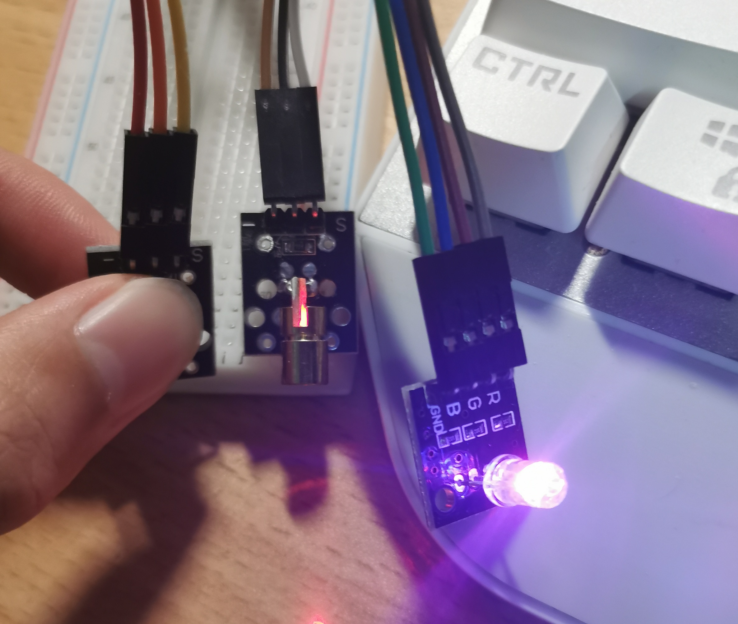
Button + RGB + laster
加了个激光玩,it’s so easy
接下来就要加些传感器了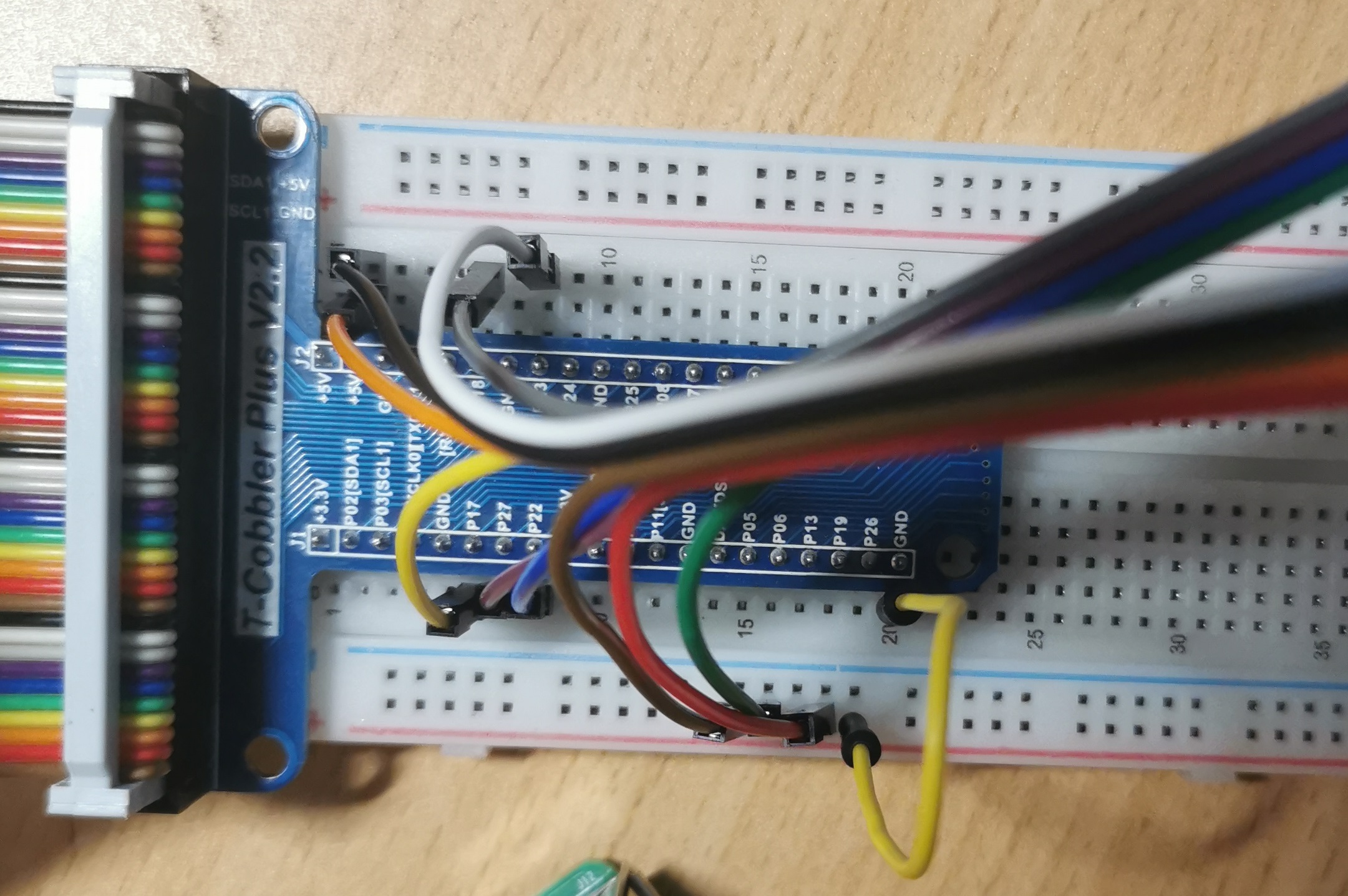
1
2
3
4
5
6
7
8
9
10
11
12
13
14
15
16
17
18
19
20
21from gpiozero import Button, LED
from time import sleep
ledr = LED(18)
ledg = LED(27)
ledb = LED(22)
btn = Button(17)
laster = LED(23)
ledb.on()
while True:
if btn.is_pressed:
ledr.on()
ledg.off()
laster.on()
else:
ledg.on()
ledr.off()
laster.off()
光敏传感器
1 | from gpiozero import LightSensor |
温度传感器 DS18B20
1 | dtoverlay=w1-gpio-pull,gpioin=4 |
火焰传感器 气体烟雾传感器 MQ-2
检测到时时输出低电压,value=1, is_active=False1
2
3
4
5
6
7
8
9
10from gpiozero import InputDevice
from time import sleep
mq2 = InputDevice(27)
fire = InputDevice(22)
while True:
print(mq2.value, mq2.is_active, fire.value, fire.is_active)
sleep(0.2)
AD/DA转换PCF8591
sudo raspi-config 打开I2C和SPI, 然后sudo apt-get install i2c-tools python-smbus 安装依赖
1 | #------------------------------------------------------ |
这个文件编译一下python3 -m PCF8591.py,然后在__pycache__里面可以找到.pyc,移出来供下面的文件使用
输出烟雾传感器数据1
2
3
4
5
6
7
8
9
10
11
12
13
14
15
16
17
18
19
20
21
22
23
24
25
26
27
28
29
30
31
32
33
34
35
36
37
38
39
40
41
42
43
44
45
46
47
48
49
50
51
52
53
54
55
56
57
58
59
60
61import PCF8591 as ADC
import RPi.GPIO as GPIO
import time
import math
DO = 17
Buzz = 18
GPIO.setmode(GPIO.BCM)
def setup():
ADC.setup(0x48)
GPIO.setup (DO, GPIO.IN)
GPIO.setup (Buzz, GPIO.OUT)
GPIO.output (Buzz, 0)
def Print(x):
if x == 1:
print ''
print ' *********'
print ' * Safe~ *'
print ' *********'
print ''
if x == 0:
print ''
print ' ***************'
print ' * Danger Gas! *'
print ' ***************'
print ''
def loop():
status = 1
count = 0
while True:
print ADC.read(0)
tmp = GPIO.input(DO);
if tmp != status:
Print(tmp)
status = tmp
if status == 0:
count += 1
if count % 2 == 0:
GPIO.output(Buzz, 1)
else:
GPIO.output(Buzz, 0)
else:
GPIO.output(Buzz, 0)
count = 0
time.sleep(0.2)
def destroy():
GPIO.output(Buzz, 0)
GPIO.cleanup()
if __name__ == '__main__':
try:
setup()
loop()
except KeyboardInterrupt:
destroy()
接线的话,AO口接PCF的AIN0,一开始还不会接,因为我没有male-to-male的线,最后发现那上面的一个东东可以把俩female接起来=-=
SDA SCL就接树莓派上的SDA SCL
先这样,传感器目前也只用这些,其他的也都大同小异接线基本都提到过了,后面就是要看看RPi.GPIO的文档,gpiozero入门海星,功能太少,很多都不支持
参考
- 《树莓派开发实战(第2版)》